Post Processor
This section explains some tips related to generating programs for Brooks robots.
Tool Center Point (TCP)
The Tool Center Point (TCP) in RoboDK and the one defined in the robot's controller must match. If you are using a gripper mechanism, it is required to add a TCP using “Add Tool (TCP)” that is at the expected position. The new tool TCP should match the gripper mechanism TCP. Information related to the Tool Center Point (TCP) of the Brooks PreciseFlex robots can be found by going to the Web Interface and following these steps:
1.Admin
2.Setup – Parameter Database
3.Robot
4.Joint/Cartesian control
5.Dynamic Parameters
6.DataID 16051
Gripper
See the previous section Gripper Simulation on how to properly define gripper instructions compatible with the post processor. This approach properly defines locations in the GPL project, avoiding unexpected movements of the gripper’s axis/axes.
The Brooks PreciseFlex IntelliGuide grippers available are:
1.Brooks PreciseFlex IntelliGuide s23
2.Brooks PreciseFlex IntelliGuide s60
3.Brooks PreciseFlex IntelliGuide s23D
4.Brooks PreciseFlex IntelliGuide v23
5.Brooks PreciseFlex IntelliGuide v60
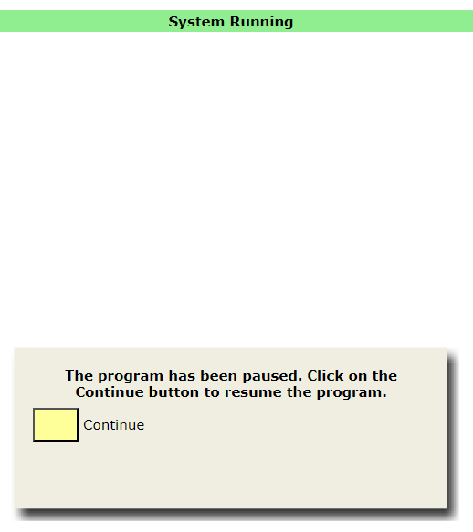
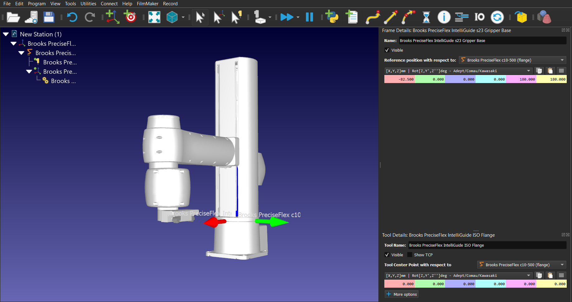
The Base Reference frame of each one of the grippers above is uniquely defined. To properly place the grippers with respect to the Flange Reference Frame of the robots, the following Reference position information must be used:
IntelliGuide s23 | IntelliGuide s60 | IntelliGuide s23D | IntelliGuide v23 | IntelliGuide v60 | |
PreciseFlex 400 | [0.603,0,0,0,0,0] | N/A | N/A | [0,0,0,0,0,0] | N/A |
PreciseFlex 3400 | [0.033,0,0,0,0,0] | [0.033,0,0,0,0,0] | [0.033,0,0,0,0,0] | [-0.57,0,0,0,0,0] | [0,0,0,0,0,0] |
PreciseFlex DD 4-axis | [-70.5,0,0,0,180,180] | [-70.5,0,0,0,180,180] | [-70.5,0,0,0,180,180] | [-71.1,0,0,0,180,180] | [-71.5,0,0,0,180,180] |
PreciseFlex c10 | [-82.5,0,0,0,180,180] | [-82.5,0,0,0,180,180] | [-82.5,0,0,0,180,180] | [-82.5,0,0,0,180,180] | [-82.5,0,0,0,180,180] |
PreciseFlex c3 | [0.313,0,0,0,0,0] | [0.313,0,0,0,0,0] | [0.313,0,0,0,0,0] | [-0.291,0,0,0,0,0] | [0.279,0,0,0,0,0] |
PreciseFlex c3x | [-14.655,0,0,0,0,0] | [-14.655,0,0,0,0,0] | [-14.655,0,0,0,0,0] | [-15.258,0,0,0,0,0] | [-14.688,0,0,0,0,0] |
PreciseFlex c5 | [113,0,0,0,0,0] | [113,0,0,0,0,0] | [113,0,0,0,0,0] | [112.4,0,0,0,0,0] | [113,0,0,0,0,0] |
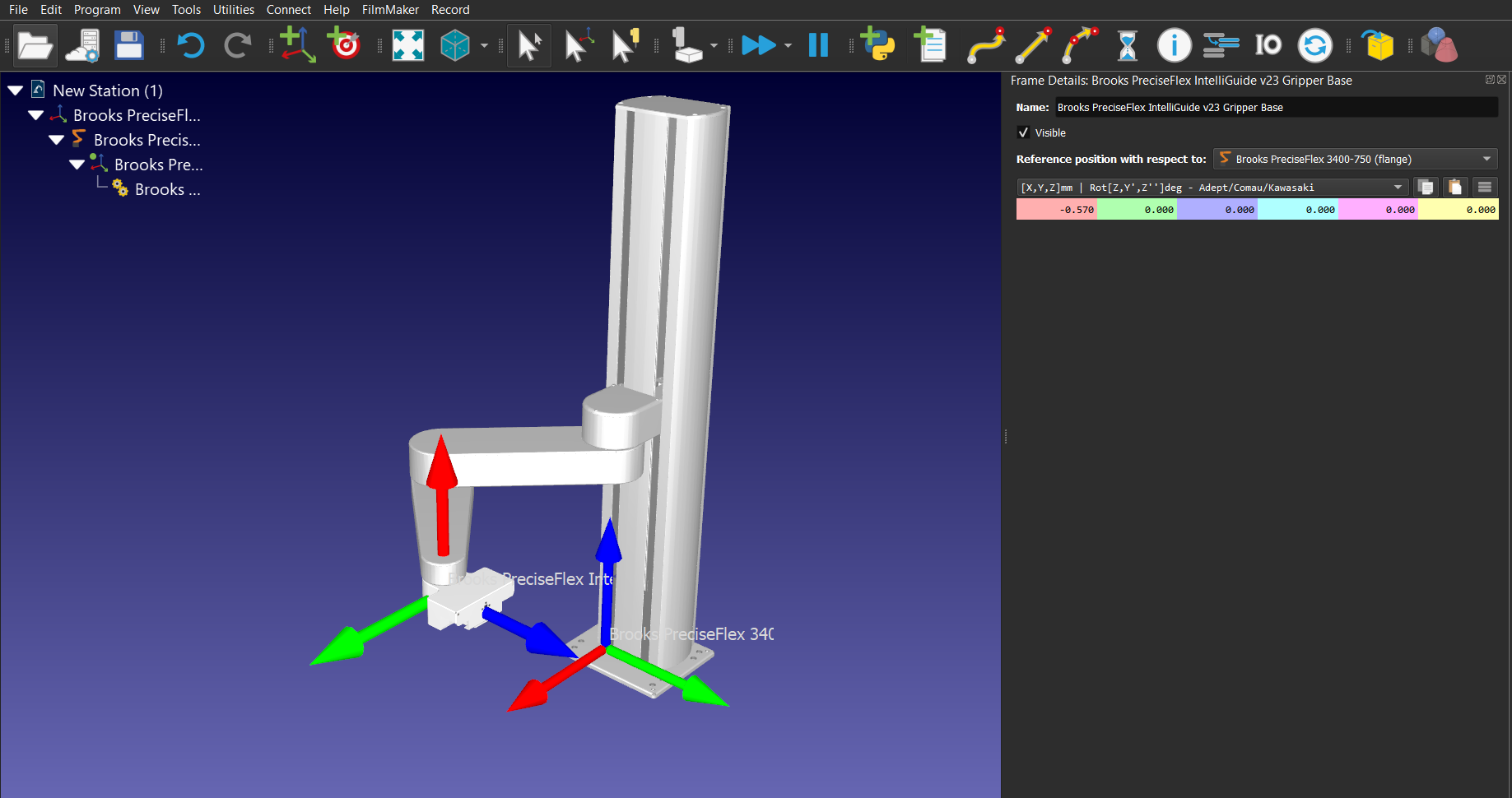
For what concerns Brooks PreciseFlex DD 4-axis and c10 robots, the IntelliGuide ISO flange available in the Robot Library must be added to the robot for visualization purposes (for the DD 4-axis robot, the IntelliGuide ISO flange geometry must be moved up by 9mm).
Rounding
An input value of -1 determines that the robot will stop at the end of the motion and a stringent position error constraint will be applied (GPL code: prof1.InRange = 100).
An input value of 0 determines that the robot will stop at the end of the motion, but a small position error constraint will be applied (GPL code: prof1.InRange = 10).
An input value greater than 0 determines that the robot will not stop at the end of the motion and a blended movement will be executed (GPL code: prof1.InRange = -1).
Speed and Acceleration
Information related to the maximum linear, angular, and joints speeds/accelerations of the Brooks PreciseFlex robots can be found by going to the Web Interface and following these steps:
1.Admin
2.Setup – Parameter Database
3.Robot
4.Joint/Cartesian control
5.Dynamic Parameters
6.DataIDs 2700, 2701, 2702, and 2703
The user can set the inputs of the RoboDK speeds/accelerations instructions using the values of the above DataIDs as references. The Precise post-processor will then use these values to calculate speed/acceleration as percentages of the maximum speed/acceleration for each robot, as requested by the GPL Profile class.
To change the limits used by the post processor, you can modify the post processor according to the specific robot you are using. By default, the post processor uses the limits of the PreciseFlex 400 and PreciseFlex 3400 robots. Refer to the https://robodk.com/doc/en/Post-Processors.html#PPEditor section of the documentation to modify the post processor.
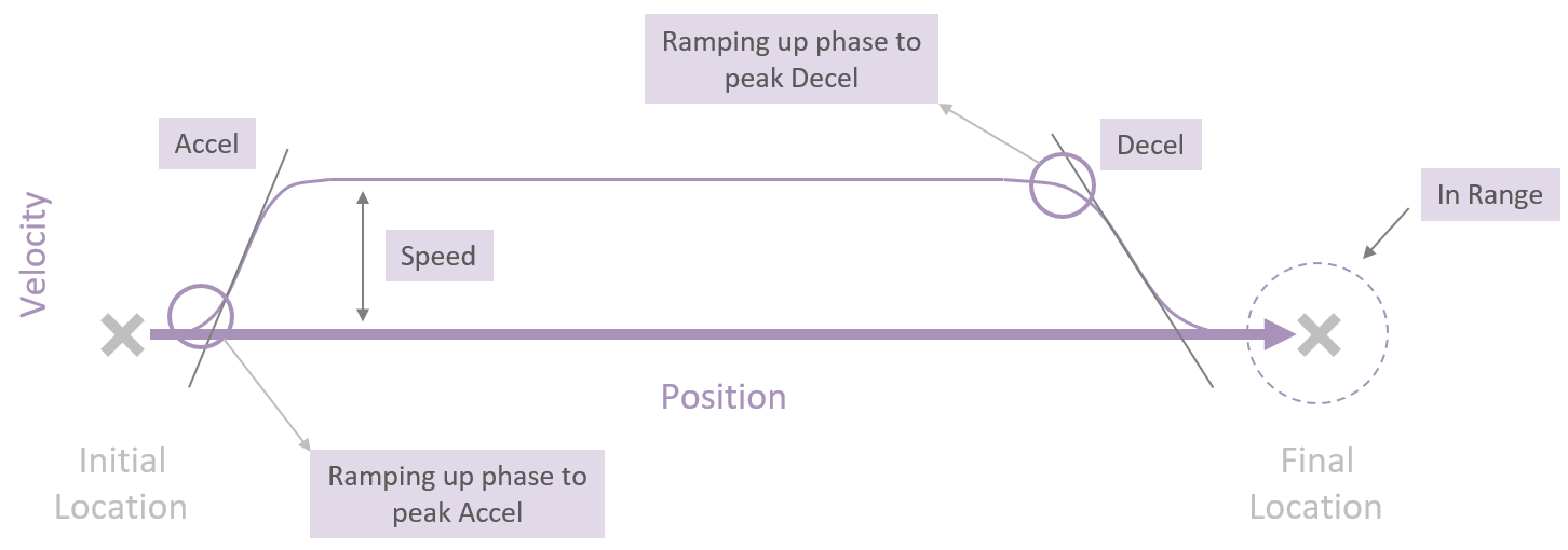
If input values less than 1 are used with linear and angular acceleration instructions, these inputs will be used as the duration in seconds for ramping up to the peak acceleration/deceleration (GPL code: prof1.AccelRamp/prof1.DecelRamp = inputvalue).
The image below gives further information related to the concepts written above and how the controller plans the trajectories that the robot must follow.
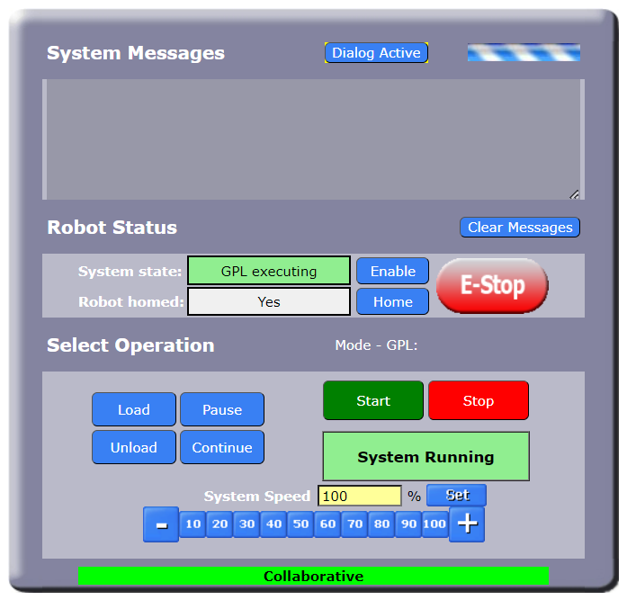
Pause
Setting an input value bigger than 0 will generate a GPL command that will pause the program for the time defined by the input value. A negative input value will open a pop-up dialog box on the Web Interface Operator Control Panel and the program will be paused until the user clicks on the “Continue” button on the dialog box. To visualize the dialog box, the user needs to click on the “Dialog Active” button on the Operator Control Panel.